


The Silent Infrastructure of the Future: Open Power Electronics Tools Behind EVs, Fast Chargers, and AI Datacenters
- Srihari Maddula
- Nov 5, 2025
- 4 min read

Updated: Nov 11, 2025
When you read news about electric vehicles, AI datacenters, or renewable energy systems, the focus is usually on batteries, compute power, or sustainability.
Almost nobody talks about the one engineering discipline quietly enabling all of it — high-voltage embedded systems development and power electronics design.
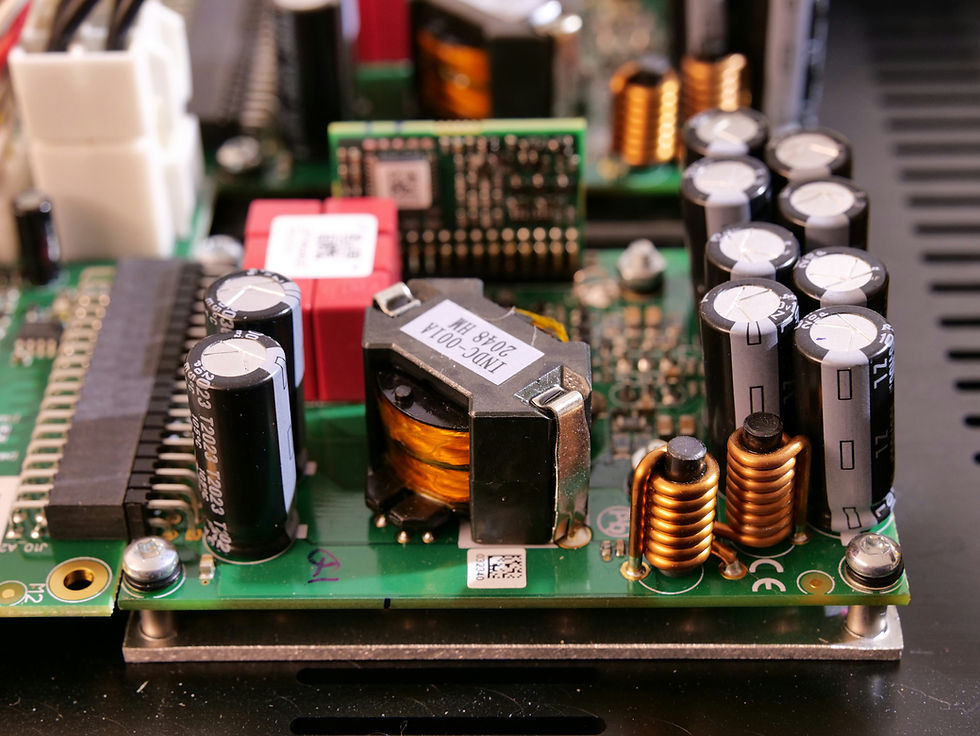
Every EV charger, solar inverter, GaN server supply, and AI power stage depends on switching devices handling thousands of volts and tens of kilowatts — operating within millimeter-level tolerances and microsecond margins.
Here, failure isn’t a reboot. Failure means smoke, arc flash, or blown silicon — destroying modules worth lakhs in milliseconds.
That’s why smart infrastructure solutions depend on verified, simulated, and open-source power design — not guesswork.
But that world has shifted.
Today, engineers can model converters, magnetics, thermal paths, motor drives, gate ringing, parasitic and even creepage/clearance — using free or open-source tools. And those tools are quietly powering the engineering behind EVs, renewable energy systems and ultra-efficient AI power infrastructure.
Here is how the power engineers of the future are working.
When a Switching MOSFET Is All That Stands Between You and Failure
Power electronics appears simple — until you design it.
One parasitic inductance and your MOSFET rings to 80 volts above spec. One bad PCB trace and your SiC device oscillates itself to death. One wrong isolation distance and an EV charger fails compliance.
To avoid this, engineers simulate the system long before the first PCB is soldered.
The workhorse is LTspice — arguably the most used SMPS simulator in the world. Engineers create a switching stage, add gate drivers, parasitic inductances, soft-start behavior, transformer leakage and transient loads. It shows what no datasheet ever fully reveals: real-world stress.
For multi-kilowatt converters, tools like PSIM or PLECS help simulate PFC stages, resonant converters, LLC topologies and motor drive control loops — often the heart of EV fast chargers and industrial drives.
Ngspice and Qucs-S provide SPICE-level control, including S-parameters, resonant tanks, rectifiers, and EMI concerns.
In other words: before silicon ever touches a PCB, the entire power train has already “lived” hundreds of switching cycles in simulation.
Every High-Voltage Converter Starts with Magnetics
Ask any power engineer where designs fail most often. They’ll tell you — magnetics.
The transformer or inductor is not a passive piece of metal; it is the heart of the converter. Core gaps, copper geometry, skin depth, eddy currents, flux density and insulation class all change performance.
Open-source FEM tools like FEMM allow engineers to visualize magnetic fields, saturation levels, leakage, and core losses.
OpenMagnetics, IncaMag and PowerEsim help design windings, choose cores, estimate copper losses and evaluate thermal behavior.
This is how EV chargers, solar MPPTs and GaN power supplies achieve 95–98% efficiency — losses are calculated before coils are ever wound.
High Voltage Is Not Forgiving — Isolation Saves Lives
A 400-V battery pack or a 3-phase EV charger cannot rely on guesswork for safety.
Isolation distance depends on altitude, pollution degree, material CTI, humidity, and surge requirements. That is why engineers use open creepage and clearance calculators and study IEC/UL summaries to determine spacing and insulation class.

Application notes from Littelfuse, Bourns and transformer manufacturers provide rules for:
surge protection
reinforced insulation
pulse transformers
common-mode chokes
lightning events
This is how designs pass compliance without redesign cycles.
The Motor Drive Side of the Revolution
Smart city technology partners and EV OEMs depend on motor control firmware — combining field-oriented control (FOC) and space-vector modulation.
Open tools support this too:
ST Motor Control Workbench
TI InstaSPIN Labs
GitHub repositories with FOC/SVPWM implementations
Motor inverters are now being built on everything from STM32 to GaN-based high-frequency switches. Engineers simulate switching, dead-time, shoot-through protection, and shunt current feedback — long before the first prototype spins.
GaN and SiC — Smaller, Faster, Hotter
The EV and datacenter revolution is powered by a new class of switching devices:
GaN for high-frequency and compact chargers
SiC MOSFETs for high-voltage traction inverters, solar and industrial drives
Most failures occur not in the device, but in the layout. Gate loops ring. Switch nodes overshoot. Diodes have recovery spikes. Parasitic become real.
Application notes and free modeling tools from GaN Systems, Transphorm, Wolfspeed and TI provide real switching waveforms, thermal models and layout blueprints.
This is where open knowledge stops engineers from learning “the hard way”—by blowing silicon.
EMI and Power Integrity Are Where Designs Live or Die
Your converter works on the bench? Great. Try passing EMI testing.
OpenEMS lets engineers simulate radiated emissions, cable coupling and shield performance. Sigrok and PulseView capture switching transients, ringing and shoot-through events. LTspice models parasitic inductances to predict ringing before the prototype goes to the lab.
A single ns-scale overshoot can fail EMI compliance, and open tools help catch it early.

Heat Always Has the Final Vote
GaN and SiC allow compact high-switching power stages, but thermal density skyrockets. Every watt of loss becomes heat. Every 10°C rise halves lifetime.
OpenFOAM, SimScale and PowerEsim estimate:
junction temperature
heatsink effectiveness
airflow paths
hotspot formation
enclosure cooling
Without this step, a “working” converter will fail in the field months later.
Real Testing Still Matters
When hardware finally arrives, open tools help automate torture tests:
OpenHTF for surge, power cycling, efficiency logging
PyVISA + SCPI to drive loads and capture waveforms
QEMU/Renode for firmware-in-loop testing
Because power electronics doesn’t get tested once — it gets tested until it breaks, and then redesigned so it doesn’t.
Why This Matters More Than Ever
AI datacenters are consuming megawatts. EVs are replacing combustion engines. Solar and wind are replacing coal. Fast chargers are appearing in every city. Ships, trains, aircraft and factories are electrifying.
The world is moving from fossil-fuel complexity to electrical complexity. Power electronics is the new infrastructure.
And unlike oil, electrons don’t forgive design mistakes.
Final Thoughts
Open-source and free tools have democratized high-voltage design. A small engineering team can now build:
99% efficiency GaN power supplies
SiC traction inverters
Solar MPPTs
EV fast chargers
UPS and datacenter rectifiers
Battery BMS power stages
without needing million-rupee commercial simulation suites.
LTspice simulates the converter. FEMM shapes the magnetics. OpenEMS checks EMI. OpenFOAM models thermal flow. OpenHTF automates power testing.
This is how the new generation of hardware startups and product teams are innovating — fast, accurate and safe.
EurthTech partners with EV, renewable, and smart infrastructure OEMs to design safe, power-dense, and sustainable converters — combining AI, IoT, and embedded systems development into one intelligent design process.


Comments